Restoration & Renovation
Masonry Restoration: The Ames Building
By Matthew C. Carlton and Mark K. LaBonté
Matthew C. Carlton, AIA, LEED AP, is a registered architect in the building technology department of national engineering firm Simpson Gumpertz & Heger Inc. (SGH). He has more than 14 years of experience in architecture, historic masonry restoration, investigation and New Construction Peer Review Services. Matthew is a licensed construction supervisor for the State of Massachusetts as well as a member of the Boston Society of Architects (BSA), The Association for Preservation Technology, and the American Institute of Architects (AIA).
Mark K. LaBonté, P.E., is a senior staff engineer at national engineering firm Simpson Gumpertz & Heger Inc. (SGH). Mark has more than 25 years of experience investigating building envelopes, developing remedial designs, and implementing work in the field. He has had key roles in restoration and repair of several landmark masonry buildings in the Boston, MA, area.
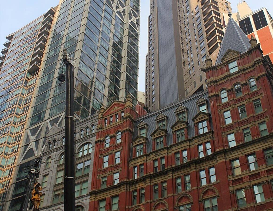
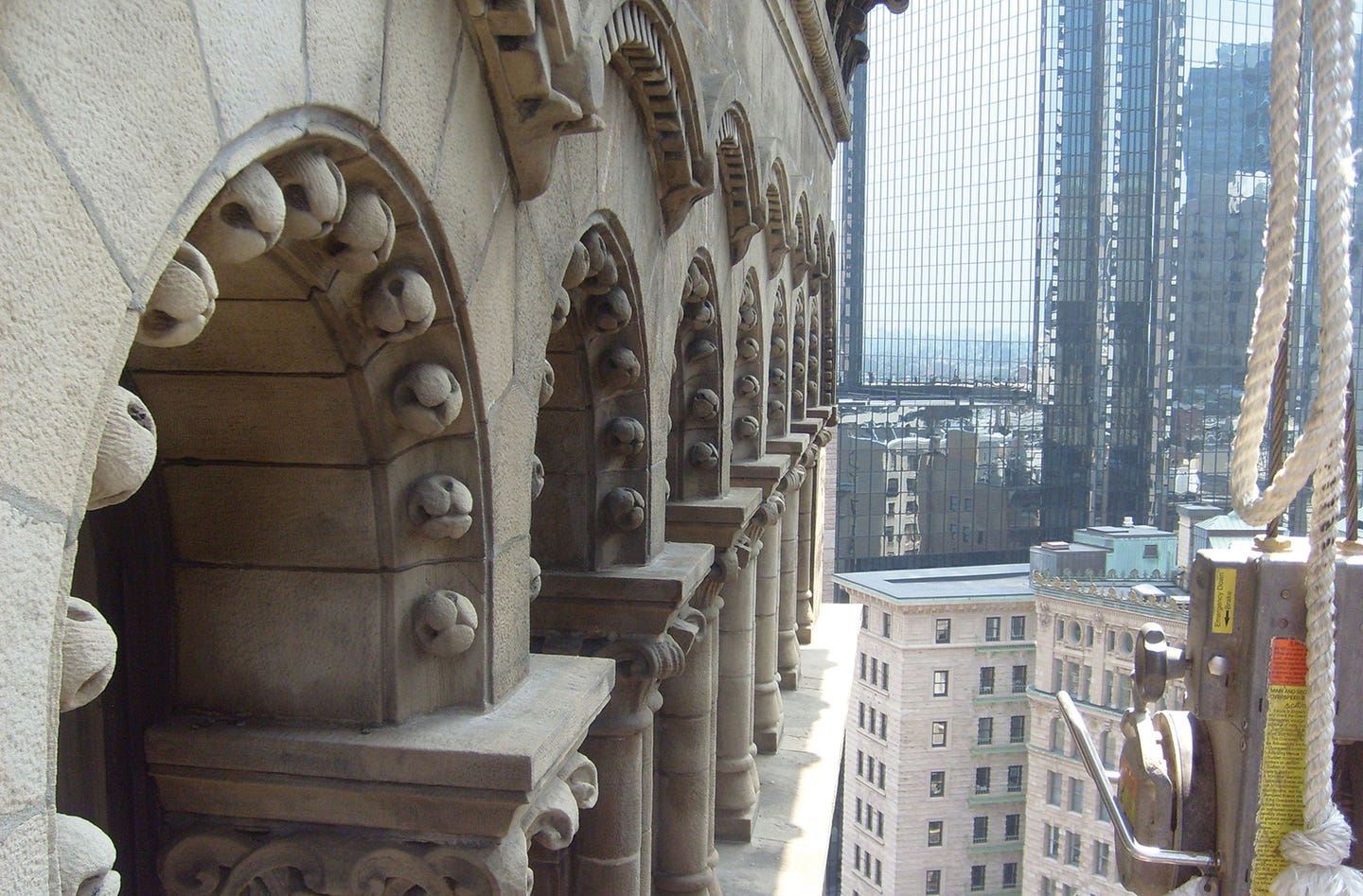
At 14 stories and 185 ft. to the parapet, Boston’s Ames building is one of the tallest load-bearing masonry buildings in the United States and Boston’s first skyscraper. Built in 1889 as offices for the Ames Agriculture Equipment Company and the Old Colony Trust Company bank, it has undergone an extensive restoration and rehabilitation, and reopened in 2009 as a boutique hotel. The building is distinguished for its beauty and intricately-carved stone facades, semi-circular arches, and architectural massing, which exemplify the Richardson-Romanesque composition.
A massive five-ft.-thick granite foundation rises to the street level where it emerges as a finished Milford granite base supporting six 30-ft. tall granite arches on two public elevations, capped by incredibly large blocks of stone forming a water-table course at the sills of the fifth-floor windows. Ohio Berea sandstone with decorative red Long Meadow and dark blue North River sandstone accents rise up another 10 stories to culminate at an impressive, intricately-detailed stone cornice.
The Ames building’s structural system is characteristic of the standard “fire-proof” construction of its era: un-reinforced masonry load-bearing perimeter walls, interior steel columns and beams, and terra-cotta arch floors.
To resist wind-driven rain and freezing temperatures, the perimeter walls provide a massive, but porous and permeable barrier at the exterior surface that breathes, taking on moisture and giving it back in annual cycles. Masonry barrier walls provide durable service as long as there is sufficient mass (thickness) to accommodate a balanced wetting and drying cycle without long-term net moisture gain. Heating the interior space during severe New England winters helps drive moisture from the walls and protects against mortar deterioration from frost expansion.
Balancing the Historic Designation
The Ames building was added to the National Register of Historic Places in 1974. Recognition of the Ames building as an historic treasure meant that development of the remedial scope of work required appropriate care and understanding of how the building’s structural and envelope barrier systems functioned. The historic qualities of the building’s public and non-public facades required not only a thorough condition survey, but also a comprehensive understanding of how the exterior walls supported themselves and resisted wind loads and other environmental conditions to remain so durable.
The condition survey, evaluation and remedial design included a considerable effort to develop the least invasive repair techniques that could address the underlying causes of deterioration as well as address the outward manifestations of deteriorated mortar, cracking, spalling, staining and other symptoms of distress.
We recorded and assessed crack patterns at sandstone lintels, columns and other bearing elements to determine the likely effects on the stability of the overall system. We used CAD drawing reproductions of the original archived drawings to note deficiencies. Some of the cracking was caused by the displacement of adjacent stone elements due to stress concentrations or movement between withes resulting in a redistribution of load paths.
Cracking and displacement in the brick masonry on the upper levels of the non-public elevations was extensive due in part to corrosion jacking of steel beams supported in bearing pockets in the exterior walls below the roofing. This distress was initiated by the minimal cover of masonry withes outboard of the steel and compounded by water penetration past the initial cracks and deteriorated mortar, and later by failed roofing at the inboard side of the parapets. This and the lateral expansion, ratcheting of the parapets (parapets expand but rarely contract) at the top of the non-public elevations made up the worst of the masonry distress.
Engineers and masons worked together to develop appropriate mortar mixes to match the original mortar color and strength, to identify the extent of distressed masonry, and to salvage as much brick as possible. Spalled, cracked or displaced bricks were located and replaced in kind.
Several deteriorated and displaced lengths of brick masonry wall and parapet at the roof levels were disassembled. Generally, the corners had displaced from the building forming step cracks where the movement was measurable in the offsets from the plane of the walls on adjacent elevations. These wall areas were reconstructed in kind and strengthened with 1/2-in. stainless steel threaded rods placed horizontally in the bed and collar joints, around the corners, beyond the step cracks into sound masonry.
Most of the mortar deterioration, cracking, staining and distress in the stone on the public facades were due to water penetration that had likely started as a small defect. These walls had functioned effectively for most of the previous 100 years, so the envelope repair tasks generally were to locate problems, determine the extent of the deterioration, and restore original conditions. We went about locating deteriorated mortar, sampling the depth of deterioration, and developing mix designs for pointing repairs. Similarly, we developed protocols for sandstone crack repairs using compatible cementitious patching mortar in various colors to match variations in the sandstone.
Spalling, erosion and exfoliation of stone surfaces was generally confined to the red and blue sandstone elements included in decorative courses between the 9 and 12 floors, and, to a much lesser extent, in areas of the Ohio sandstone beneath the cornice. Overall, the siliceous stone from Ohio with multiple surfaces exposed by the intricate carving fared better than the less durable stone set in the plane of the wall. This Ohio sandstone deterioration is likely caused in part by repeated differential wetting/drying cycles and frost expansion, while the deterioration of the red and blue elements is exacerbated by acid rain or mineral migration in the stone strata.
When a porous stone is wetted, it swells, developing internal stresses between areas of different moisture content in a manner similar to the stresses created by temperature differentials. These stresses can form microscopic crevices resulting in the detachment of the binder that holds the system together. Acid rain will chemically change some binder materials from an insoluble to a soluble form, susceptible to erosion. Most of the detachment was superficial so we decided the least invasive process was to remove loose pieces and scrape away exfoliated material back to sound surfaces
The structural repairs of significant masonry cracks included epoxy injection and, in some instances, embedment of threaded steel rods. Various viscosities of two-part epoxy were selected based on crack width and depth to be injected into the crack using a bulk caulking gun, working up the crack, after sealing the surface with silicone sealant and placing plastic injection ports at uniform spacing the length of the crack. After the epoxy had cured, masons removed the ports and the sealant and routed out the surface of the crack to receive a proprietary cemetitious patching material that matched the color and texture of the surrounding stone.
Some of the larger cracks required retrofitting up to 5/8-in. dia. stainless-steel rods, inserted across the cracks and embedded in epoxy. These reinforcing pins were installed without removing the stone by drilling through the stone face at a 90- or 60-degree angle across the crack into the stone. Engineers worked with the masons to develop techniques to assure that the rods were fully embedded in epoxy and to patch the holes at the surface of the stone to match the stone color and texture.
Points to Consider When Restoring Masonry
Renovation of old masonry-bearing wall construction has its challenges, which vary based on the original selection of materials, the skill of the masons, and the level of maintenance performed over the life of the building, particularly the recent past if the building has been out of service. The following are points to consider on your next project:
- Review the deterioration up close and personal to view each mode and determine how moisture migration and movement of envelope elements are affecting adjacent structural elements. These conditions will provide clues to the least intrusive, though most holistic, repair design.
- During the building survey, remember to review the roof perimeter. If the roofing is failed or leaking, get it fixed. Few defects can destroy an old building quicker than a leaking roof.
- Identify the mortar type and constituents and probe the depth of deterioration.
- Determine the exact stone geology for all elements on the building. This information will guide your repair design.
- Make exterior wall probes to determine the depth of stone elements, such as lintels and water tables. Don’t rely solely on original architectural details, as they may vary.
- Assemble a design team consisting of building technology experts and structural engineers for an holistic approach to the repair of the building.